
Memo 0004: A ½-wave coaxial notch filter for 1.7 to 1.9GHz
Canadian Centre for Experimental Radio Astronomy http://www.ccera.ca
Memo: 0004 A ½-wave coaxial notch filter for 1.7 to 1.9GHz
To: Interested parties
Cc: Open Source Radio Telescopes
From: Marcus Leech, mleech@ripnet.com
Date: Oct 21, 2017
Subject: A notch filter design for 21cm use
This memorandum describes the design and build of a ½-wave coaxial notch filter for use in 21cm systems where interference from cell provider transmitters in the 1.7 to 1.9GHz range may be an issue.
Notch filters
Transmission line theory tells us that any odd multiple of ½-wavelength transmission line will act as an impedance repeater That is, an impedance that is presented on one end of the line will be seen at the other end.
The same theory tells us that a ¼-wavelength (or multiples thereof) transmission line is an impedance inverter—the impedance seen at one end is the reciprocal of the other.
Either of these properties may be used to produce very simple filters from ad-hoc coaxial transmission line elements.
It is convenient for our purposes to use a ½-wavelength construction for two reasons:
- The resulting filter is larger, thus reducing the inevitable construction measurement error that creeps in to practical designs.
- The filter is a DC short, thus providing excellent protection for any LNA inputs downstream of the filter.
Now a notch filter is one that produces a stop band effect when placed into a transmission line. Frequencies outside the stop band are passed with only very small attenuation, whereas frequencies within the stop band are significantly attenuated.
Mobile communications frequencies
There are several frequency allocations that are close enough to the 21cm band at 1420.4Mhz to cause occasional-to-frequent grief to radio telescopes operating at these frequencies.
Most of these frequencies are in the range 1.7GHz to 2.1GHz.
It should be possible to build a single-element notch filter to be placed in front of the first LNA element that has adequate rejection at the desired notch frequency, and sufficiently-low loss at the desired pass frequency.
Construction materials
Most coaxial filters of this type use an outer tube of copper, aluminum, or brass, with either a square or round profile. We’re using square aluminum tubing, with 1.5” x 1.5” with 0.125” wall thickness. The resonator, or central conductor is usually made of brass or copper. Our present design uses a brass tube, 3/8” OD. This gives a characteristic impedance in a square tube of roughly 77 ohms. The characteristic impedance of a shorted-stub filter of this type can range between 40 and 90 ohms, with only minor differences in performance. In the case of a stop-band design, the stub itself “looks” like a very high impedance outside of the stop-band, and very low impedance inside it—the characteristic impedance is less critical. Considering the “pass band” part of the analysis, one can imagine a 50-ohm transmission line, with an impedance of several k-ohm in shunt with that impedance. Nearly ALL of the energy will be transferred between the input and
output port, and only a very small amount will be shunted to ground. This is a simplistic analysis, but suffices to understand why simple shorted/open stubs work.
A schematic filter design in shown below:
Schematic Design
We use flange-mount type-N connectors for these filters. A male on one side, and a female on the other, affording direct-connection to the circular-waveguide feed.
The dimensions of the center conductor given above are approximate, and should allow one to build filters that are “tuned” for frequencies between roughly 1700MHz and 2.1GHz. Some experimentation will be required.
Additionally, a tuning screw can be added by drilling and tapping a #10-24 or ¼-20 hole through the side wall, approximately half way along the resonator length, and centered on the wall. Such a tuning screw can allow the filter to be peaked on the correct frequency and the pass-band VSWR adjusted.
The connection between the input and output connectors should be copper wire, 14ga or better. We use silver-plated 14ga wire that was acquired from an on-line jewelry making store. The silver plating affords slightly lower skin loss on the wire that naked copper. We show this below in our prototype filter.
Connecting the input and output
The connection to the central resonator conductor can be facilitated by cutting small slots into the end that will mate with the through-wire. Such is shown below.
Notching the central resonator to facilitate connection
The bottom plate should be made from copper sheet, with a snug hole drilled in to to accommodate the central conductor. The conductor can be made a little long so that it pokes through the bottom plate enough to facilitate soldering.
Assembling the bottom plate
The plate is affixed to the outer, square, shield using conductive copper tape. Other methods could be used, such as making the bottom plate wrap-around the shield and affixing with a number of small screws or rivets.
Once it is all assembled, it can be tested, and adjustments made, if a tuning screw was outfitted. The response of our prototype filter is given below, showing a “useful” stop-band around 1.8GHz of approximately 100MHz width.
Some experimentation will inevitably be required, and having a simple impedance meter such as the N120SA shown above makes adjusting these filters both easy and practical.
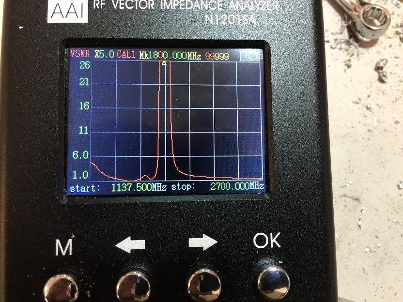
Measured filter bandpass
Shown above, you can see that the VSWR is very high in the design stop-band around 1.8GHz, but quite low (below 1.4:1) in the passband around 1.42GHz.
Conclusions
A simple ½-wave coaxial shorted-stub notch filter appears to be a reasonable design choice for targeted RFI management in 21cm (1.42GHz) radio astronomy receiving systems.