
Memo 0008: A cheap, simple FX correlator
Canadian Centre for Experimental Radio Astronomy http://www.ccera.ca
Memo: 0008 A cheap, simple FX correlator
To: Interested parties
Cc: Open Source Radio Telescopes
From: Marcus Leech, mleech@ripnet.com
Date: Apr 10, 2018
Subject: FX Correlator design and results
This memorandum describes experiments in producing a simple FX correlator for amateur interferometer instruments.
Correlators
The most common design for an interferometer receiver system in professional radio astronomy is the correlator. Fundamentally, the correlator coherently multiplies the signals arriving from each antenna in a antenna-pairing, or baseline.
In amateur instruments, it has historically been the case that certain approximations to the ideal “multiplier” case are used. One approach is the adding interferometer, in which the two signals are additively combined, as with a simple cable-TV combiner. The resulting data pattern produces a fringe-type structure, superimposed upon a slower-changing structure corresponding to the beam-shape of the antennae in use. It is a significant design compromise, since it is sensitive to both fine and gross structures in the incoming signals, which generally means that weaker, discrete, sources tend to get “swamped” by the primary beamwidth-shaped “gross structure” of spatially-distributed background.
The next-most prevalent design in many amateur instruments is the phase-switching interferometer, which approximates a multiplier (correlator) quite well, but requires somewhat arcane phase-shifters and synchronous detectors.
This author became aware of correlation receivers during a 21cm interferometer project in the mid 1980s, with the use of a H-P analog multiplier, which produced analog signals that could then be low-pass filtered and digitized.
The FX correlator
With the advent of software-defined-radio (SDR) hardware and DSP frameworks, like Gnu Radio, it is natural to re-visit the “standard approach” used by amateurs as described above.
There are several extant examples of SDR radio hardware that provide two (or MORE!) mutually-coherent channels upon which a “modern” correlator can be built.
In an FX correlator, the signal from each antenna is coherently sampled–that is, for any given pair, there exists strong phase-coherence in the underlying receiver architecture. Once sampled, the two signals are each passed through an FFT, and then bin-wise multiplied, one channel being conjugated prior to multiplication. Once they have been multiplied (correlated), they can be low-pass filtered to reduce noise variance in the resulting data product, and the data rate reduced to rates that are convenient for further science extraction.
The output of a FX correlator is a complex visibility function, but in the frequency domain, rather than time domain.
Shown below is a Gnu Radio flow-graph implementing this design.
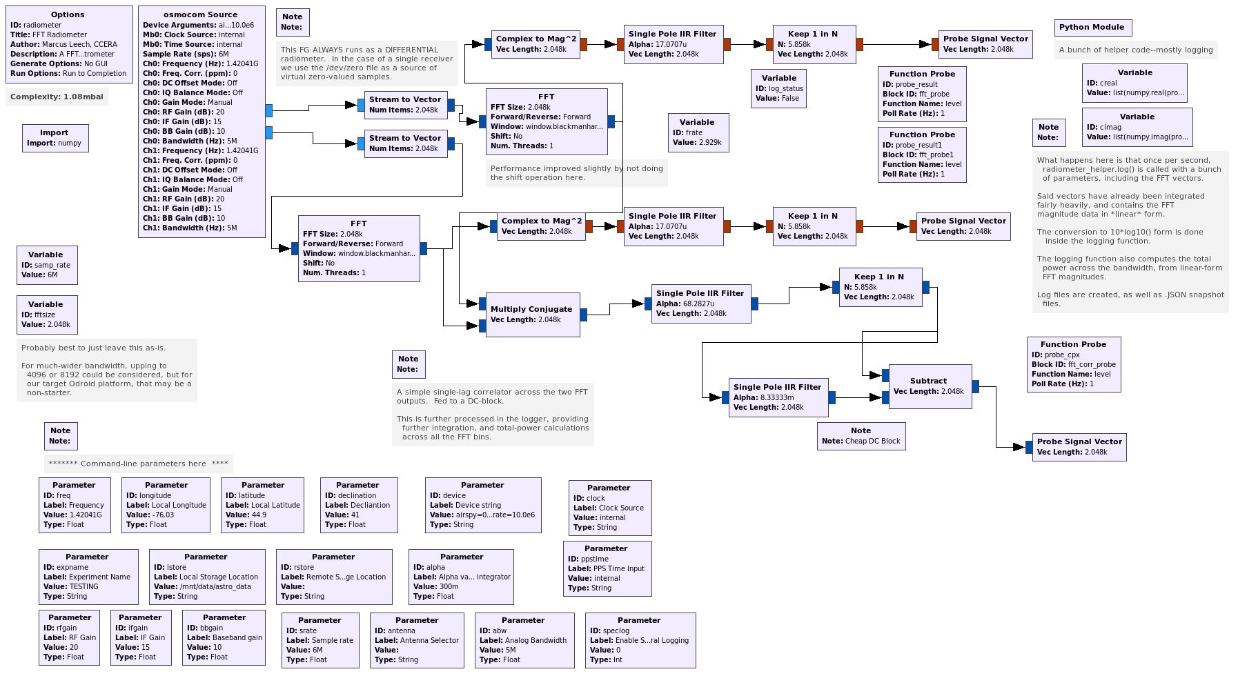
Flow graph of Interferometer components
Design Discussion
The design shown above is not particularly remarkable—no custom blocks were used, for example. The two inputs are FFTed, then various data products are formed from the FFTs. The main data pathway sends the integrated FFT outputs directly into the logging function, where further derived-products are produced.
The correlation pathway uses a multiply-conjugate operator, over a vector that is the same as the FFT size (by default, 2048 bins). The complex-visibility is then integrated, and any residual DC components eliminated through a simple integrator-based high-pass filter, the output of which goes to the logging function where further products are derived from it.
Previous Efforts
It would be unfair at this point to fail to recognize previous efforts in this area. During the beta testing phase of the LimeSDR, in the summer of 2017, David Lonard worked on an FX correlator for LimeSDR, without benefit of Gnu Radio.
From the available design discussions, it appears that the system required a PC with a GPU card for some of the bulk computations, and that it didn’t execute in real-time.
Our effort distinguishes itself in running on very cheap ARM-based single-board computers, and executing in real-time.1
Data Products
The frequency-domain representation produced by an FX correlator has a few advantages, even for the amateur observer.
- Sub-banding is straightforward and cheap. For observations where the fractional bandwidth is high enough that bandwidth-smear is a concern, this can be used to good advantage. This will typically be for observations at VHF frequencies, where even 10MHz of bandwidth could result in significant bandwidth smear.
- Narrow-band, persistent, RFI can be easily eliminated simply by ignoring FFT bins. Various data products are produced and logged by the logging function including:
- The integrated magnitude components from the FFT at each antenna
- The difference between those FFTs
- The real and imaginary components of the correlated FFTs (visibility function)
- The derived angle between the real and imaginary components
- Scalar sums over the various FFT and correlator products
System Design
The system was used with our existing 611Mhz two-element interferometer array, which has been described in another memo in this series.
Both a USRP B210 and LimeSDR have been used with the FX correlator, with similar results. A problem was noted with the LimeSDR in that it produced a large band-edge spur when programmed to provide samples at 6Msps, but not at 5Msps. We opted to continue the experiments with LimeSDR at 5Msps, with an only very-minor loss in sensitivity.
The flow-graph runs on an Odroid HC1, logging data to a local SSD disk drive, without any type of GUI interface running locally on the Odroid. This allows an approach of antennae connected by Ethernet cabling, rather than coax, data products optionally being logged not only to the local SSD (with automatic “age out” of old data) but to a CIFS share anywhere on the local network.
Work is in progress to allow real-time data status display purely through any reasonably-modern web-browser, and to allow experiment-launch a web-browser also.
Early Results
Our 611MHz interferometer array is currently pointing at a declination of +50, which is half-way between Cygnus A, and Cassiopeia A. Our hope is that this will allow us to monitor the slow brightness decay of Cassiopeia A by comparing against Cygnus A.
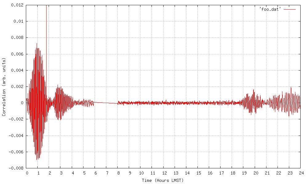
Initial results – the region between Cygnus and Cassiopeia
Shown above is a nearly-24-hours scan at a declination of +50deg. Both Cygnus A (at approximately 20:00 LMST) and Cassiopeia A (at approximately 23:20 LMST) are clearly visible, but quite distorted by the very-bright solar side-lobes. Later in the year, as both objects move into the post-sundown portion of the day, high-quality fringes will be available. The above plot is produced from the scalar sum of the real channel of the complex FFT visibility. It is interesting to note that as you use smaller and smaller subsets of the FFT bins to produce this scalar sum, the signal-to-noise ratio becomes worse and worse. This is exactly what you’d expect, given the relationship between observing bandwidth (number of FFT bins), and sensitivity.
Conclusions
An FX correlator for small-scale or amateur interferometer experiments is clearly feasible without significant expenditure on exotic hardware. Very-modest computational resources can be brought to bear on the problem, at least for sample-rates up to 10 to 12Msps, without any “store and compute” architectural requirement.
1 See: https://groups.google.com/forum/#!forum/amateur-radio-interferometry