
Marcus Leech
Science Radio Laboratories, Inc.
Abstract
We show two slightly-different designs for a simple, small, effective, radio telescope capable of observing the Sun, and the galactic plane in both continuum and spectral modes, easily able to show the hydrogen line in various parts of the galactic plane.
Introduction
The emergence of new, relatively-inexpensive tools for the RF tinkerer has allowed a re-examination of the “bottom end” of small-scale and amateur radio astronomy. Until quite recently, anyone on a very small budget, or with outdoor space constraints would likely be stuck with a simple radio telescope such as the IBT 1 . While such an instrument is an excellent device for portable classroom demonstrations of the very-basic principles of radio astronomy, this author wished to explore that space further. Specifically, the possibility of an instrument with a roughly 1m reflector, capable of observing the hydrogen line, and the continuum emissions from the galactic plane, in addition to the Sun. Since the IBT is only really capable of observing the Sun, it was felt that a richer educational experience might be realized by having a slightly-more-capable instrument within a similar budgetary envelope.
Software Defined Radio
In the past, having a radio astronomy receiver that was capable of providing spectral information was out of budgetary reach of the small-classroom environment. Fine instruments such as the SpectraCyber made by Radio Astronomy Supplies, for example, are easily affordable by most higher-education institutions, but usually not at the high-school level.
In the past few years, Software Defined Radio (SDR) has emerged as an exciting new technology that is increasingly being leveraged by amateur radio astronomers to expand their experimental horizons relatively cheaply. With an SDR, the RF signals are typically converted to so-called “baseband” form, and then digitized at one or two megasamples/ second, and then forwarded to a PC for further processing. In this way, the signals are presented in their “rawest” form, so that they may be processed in many different ways to extract different types of experimental data. With SDR, there is no hardware that is specifically dedicated to continuum observations, or spectral observations, or other types of specialized modes. All the processing happens in software, rather than analog hardware.
Software “frameworks”, such as Gnu Radio have significantly simplified the ad-hoc construction of software-based signal-processing “chains”, allow many different types of experiments to be conducted on real-time radio telescope data, using SDR receivers as input.
In early 2012, it was discovered that certain DVB-T “dongles” (USB devices intended to allow you to watch over-the-air DVB-T broadcast television) had a special “mode” that allow them to be used as crude SDR receivers. In this mode, the digital base-band samples bypass the DVB-T demodulator/decoder in the RTL2832U chip, and are sent over USB. Normally, these devices send partially-decoded MPEG transport frames over the USB, but in this “SDR” mode, they send raw I/Q base-band samples instead.
These “dongles” are typically shipped with one of two or three different tuner chips, and the most popular ones, the R820T and E4000 tuners both allow tuning to the hydrogen-line frequency of 1420Mhz.
These devices, being mass-market consumer devices, are available very cheaply, usually under $20.00 from on-line sellers on eBay, AliExpress, Nooelec 2 , etc.
A driver library was quickly produced 3 based on the information gleaned from datasheets and a bit of reverse engineering. The driver library can be used stand-alone, or in concert with a “plug in” for Gnu Radio that allows Gnu Radio applications to use the RTLSDR devices.
These devices, while quite inexpensive, have some noticeable drawbacks:
- Dynamic range is quite limited, due to use of an 8-bit ADC, roughly 45dB SFDR
- Phase and amplitude balance is quite poor, leading to image problems
- Frequency accuracy is extremely poor, typically +/- 70PPM or worse
- Phase noise, due to the poor crystals used, is also very poor
- Temperature stability is poor, leading to gain drift, and frequency drift
- Shielding is non-existent, so you have to add that yourself
Despite all of the above, it’s possible to obtain entirely-adequate results with appropriate “aftermarket” re-engineering of the devices.
Hardware: Ettus Research B100+WBX combo package Since 2005, Ettus Research have been designed and manufacturing a growing line of Software Defined Radios that offer extremely good performance at very competitive prices. Unlike the RTLSDR hardware described above, the Ettus radios are purpose-built for SDR applications.
Comparing the B100+WBX combination package to the RTLSDR:
- Higher dynamic range, using 12-bit ADCs, giving roughly 70dB of SFDR
- Much better frequency precision: +/- 2.5PPM
- Much lower phase noise
- Much better phase/amplitude balance
Shielded enclosure
The author has used Ettus hardware in radio astronomy projects since 2005 and finds that they are an exceptional value.
The radios are priced as you might expect for a “niche market” item intended for technology developers, however, in that market they are extremely competitively priced. For a school wishing to get noticeably-better results, the Ettus B100+WBX 4 combination package is an excellent choice.
Hardware: ~1m offset dish
The IBT uses an offset-fed satellite dish that is typically 0.5M in diameter or somewhat larger. While such a dish affords excellent portability, the aperture is somewhat too small for sensitive observations of the galactic plane at 21cm.
The author has achieved excellent results using an offset-fed satellite dish, measuring 93cm x 85cm, and it is suggested that experimenters try to find a dish of roughly this size. Such small, offset-fed dishes are available online 5 from a number of online satellite retailers as well as eBay. In many large cities, there are still “brick and mortar” satellite equipment retailers where such dishes may be purchased reasonably cheaply.
Occasionally, you may find people discarding these dishes, having migrated back to cable television away from satellite television. It’s important that any dish acquired include the feed-arm hardware. There are also many “package deals” that will sell you a dish and a Ku-band LNB. The Ku-band LNB may be used in other experiments, but primarily it helps to give a good notion of how to position the 21cm feed-horn assembly that is described later in this article.
The feed-arm hardware will have to be modified to accommodate the much-larger 21cm feed-horn assembly.
Alternative hardware: ~1m prime-focus dishes There are also small prime-focus dishes available from some places, roughly 1.3m in diameter. These have the advantage that they’re easier to point, but are generally significantly more expensive, and harder to find, than the offset dishes of roughly the same diameter. Manufacturers such as Jonsa and Foretec Star 6 make such dishes, but it can often be hard to find local distributors. The feed assembly for these dishes is less complicated to make as well, since they tend to be deeper (0.38 to 0.42 F/D).
Hardware: Feed assembly
The feed assembly will have to be hand-made. Fortunately, making one is very straightforward. We start with a so-called “2lb” tin-plated coffee can. These cans are 6” in diameter, and usually 7” to 8” tall, containing 2 to 2.5lb of coffee. You’ll need to empty the can, either through gradual consumption of the contents, or something a bit more draconian.
The cans are usually sealed with a thin aluminum membrane as well as the plastic lid. If making a feed for a prime-focus/deep dish, retain the plastic lid, it will make a useful weather cover. Once you’ve removed the sealing membrane, there will be a little ring of aluminum still attached to the can. Use a can-opener to remove it. Wash and dry the can using a bit of dish soap.
Drill a hole through the side of the can for your chosen connector. Type ‘N’ is popular, but this author used a tin-plated type ‘F’ since all his “plumbing” is type-F compatible. The hole should be 3” from the bottom of the coffee can, as shown below. If you’re using a tin-plated type ‘F’ bulkhead or PCB edge-mount connector, you can solder the connector directly to the coffee can. You’ll need to use a soldering-gun to do that to provide the extra heat that will be necessary.
If you use a type ‘N’ or other connector, you’ll have to drill holes as appropriate. Choose a connector that is compatible with whatever LNA you’ll be using, with minimum adaptors required, to reduce front-end losses.
One thing to note is that drilling thin steel sheet requires considerable care, and it’s usually necessary to step your drill sizes up gradually, so as not to try to remove too much material at a time. You’ll need to solder a probe to the center conductor of the connector, approximately 1.8” long, and made from 10 or 12-gauge copper wire. Brass tubing also works well.
Layout of the feed assembly
If using a prime-focus dish with a F/D of 0.38 to 0.45, the coffee-can feed alone is sufficient to produce acceptable results. Put the plastic lid back on, and cut a small “cross” with a sharp knife in the middle of the lid—this allows pressure equalization so you don’t get moisture “pumping” into the can interior.
Before you do this, you can also give the can exterior and interior a couple of light coats of clear lacquer spray-paint – this will slow down the inevitable corrosion of the steel. Don’t forget to tape-offthe connector when you’re doing this!
If using a shallow offset-fed dish, you’ll need to augment the coffee-can feed with a pair of tapered adapters that increase the gain of the feed, to properly illuminate the dish. Go to your nearest HVAC equipment/ducting supplier and get a 6” to 8” round galvanized tapered adapter, and another 8” to 10” adapter. If you can, get the type that are crimped on one side, so that they mesh together easily. Otherwise, you’ll need to use tin-snips to create a few slots—one set to allow the 6” to 8” adaptor to fit the coffee can, and the other to allow the 6” to 10” adaptor to fit into the 6” to 8” adaptor. Once you have them all fit together it should look, in profile, roughly like this:
The feed assembly may require flared adaptors.
Drill some small holes, and use self-tapping 3/8” long, #6 sheet-metal screws to hold all pieces together. Use them liberally to improve mechanical rigidity, and electrical conductivity between all the pieces.
Again, apply a couple of light coats of clear lacquer to the assembly (although tape the connector, since you don’t want to make it non-conductive). A sheet of clear polyethylene over the end will keep birds from wanting to nest in the feed. Make sure there’s a small vent hole somewhere.
Hardware: Feed Arm Modifications
If using an offset-fed dish, modifications to the feed arm assembly will be necessary to make sure that the focus is in the middle of the 10” throat of the feed. Some amount of inventiveness will be required here, since the feed-arm arrangements are different on different dishes.
On the authors 93cm offset dish, there’s a single support arm that comes from behind the dish around to the front. Removal of roughly 12cm of feed arm allowed for the 10” horn throat to be at roughly the correct location at the focus.
The feed should be aimed so that it’s pointing at just below the center of the dish. Again, a certain amount of inventiveness will be required, and it’s likely that post-construction signal measurements will need to be made to optimize the feed location and pointing. If all the feed hardware was supplied for the dish, along with a cheap LNB, you can use that as a guide as to where the focal point is, and adjust accordingly for the much-larger feed-horn for 21cm.
The author uses an L bracket attached to the front of the feed, and bent so that the feed points at the correct location on the dish, with the other side of the L bracket attached with band clamps to the feed arm.
Hardware: Low Noise Amplifier (LNA)
It is vital that the first stage of amplification in a radio telescope have as little self-noise as practical. This is known as the Noise Figure of the amplifier. Since the signals we’re looking for are very faint, having a low noise figure improves our chances of detecting them. In selecting a low-noise amplifier it should be:
- < 1dB noise figure (NF) > 20dB gain
- Ideally, it should be filtered to allow only the 21cm band to pass
- Optionally, it can be powered via the output connection, so that DC can be fed up the coax. Such LNAs are available from a few suppliers on the Internet, including Radio Astronomy Supplies, and Down East Microwave.
Hardware: Line amplifiers
You’ll very likely need two more stages of amplification before the signal is presented to your receiver. The most convenient method is to use CATV/SAT-TV “line amplifiers” that offer between 10 and 20dB of gain, but have poor noise figures. These units are usually available for about $5.00 each, and are powered over the coaxial connection on their output.
If you choose to power the amplifier-chain via the coax, it is also necessary to obtain a DC power injector—available from the same suppliers as the line amplifiers.Hardware: Coaxial cabling The author has a distinct preference for 75-ohm, RG-6Q cabling, because is of sufficient quality, and low-enough cost that it can be used in longer cable runs. The CATV/SAT-TV “ecosystem” that produces RG-6 cabling and assorted connector technologies has a lot of good bits of “plumbing” that are both inexpensive and high-quality. Compression connectors, for example, have completely changed the 75-ohm small-cable world from “rather cheesy” to first-rate. Which was a necessity when those cabling systems started to be used for SAT-TV systems.
RG-6 and RG-6Q (quad-shielded RG-6) cable is available at most hardware stores, including Home Depot, Lowes, etc. They also usually have the specialty compression connector tooling and connectors available, although on-line dealers of such equipment generally offer much better prices.
Hardware: A PC computer
You’ll need a computer to process the data coming from the receiver, and do useful things with it. While you don’t need the “latest, high end gaming machine”, you should avoid pulling something out of the trash bin for your SDR-based radio astronomy experiments.
A dual-core system of ca 2010 to 2012 vintage, running at 2.8GHz or better, with at least 2GB of ram is recommended to support the Gnu Radio software that this author uses.
The author runs the observing software on his AMD Phenom II X4 system, which has 3GB of ram, and runs at 3.2GHz. It consumes about 1/3 rd of that system in terms of CPU resources, at 1.5Msps sample rate.
For both Ettus hardware and the RTLSDR, you’ll need a spare USB-2.0 port available on the system.
Hardware: Putting it all together
Once you have assembled all the individual pieces, including mounting the dish on an appropriate platform, it’s time to this collection of parts into a cooperating observing system.
Here’s a diagram showing the overall layout:
 Schematic layout of the final assembled components
You may be able to eliminate one of the line amplifiers if you have a shorter coaxial cable run to your observing station. And you’ll need RF connector adaptors—exactly which ones depends on your choices of cabling systems, etc, and which SDR you chose.
Software: Linux: The system of choice for science the world over
The author is an unapologetic Linux zealot. The suggestion would be to install a recent Ubuntu (12.04) or Fedora (17) on whatever PC you’ve chosen to use. There are install guides all over the web for this, and the install CDs are usually fairly easy to use.
Installing Linux will make your life easier from the perspective of installing the other software components that follow.
Once you’ve installed, apply any updates it suggests, which it probably will ask for right after installation.
Software: Gnu Radio: The Signal Processing Framework
The author has exclusively used Gnu Radio for conducting radio astronomy experiments using SDR hardware since 2005. It is a flexible and feature-rich framework for constructing “radios” from collections of underlying primitive signal-processing blocks. While the signal-processing needs of amateur radio astronomy are quite modest, the Gnu Radio framework allows a large class of experiments to be conducted quite easily.
Once you have a Linux OS installed (Ubuntu and Fedora are likely the least-painful choices), you can use the “build-gnuradio” script to install the latest Gnu Radio and hardware-driver plugins from the source code repositories.
Use the script at: http://www.sbrac.org/files/build-gnuradio This script will take quite some time to run. So have a coffee (which you should have plenty of at this point), or maybe two or three. You might even want to consider a quick vacation to West Virginia or something while it’s running also, but that’s up to you.
You may also need to install “pyephem” via, pip-python: pip-python install pyephem
If your system doesn’t have pip-python, then you’ll need to install it first, using your package-manager. The package name is usually “python-pip”.
Software: The simple_ra Gnu Radio application
Recall that we referred to Gnu Radio as a signal-processing framework. It isn’t in and of itself an application, but rather is used to build applications that do PC-based signal processing.
The simple_ra application is maintained at the https://www.cgran.org site which has many applications that use the Gnu Radio framework.
Installing simple_ra is fairly easy. First: svn co https://www.cgran.org/svn/projects/simple_ra This will create a directory called simple_ra. You then just need to make/install it:
cd simple_ra/trunk
make
make install
There is a README file in the trunk directory that you are STRONGLY encouraged to read.
Preliminary results
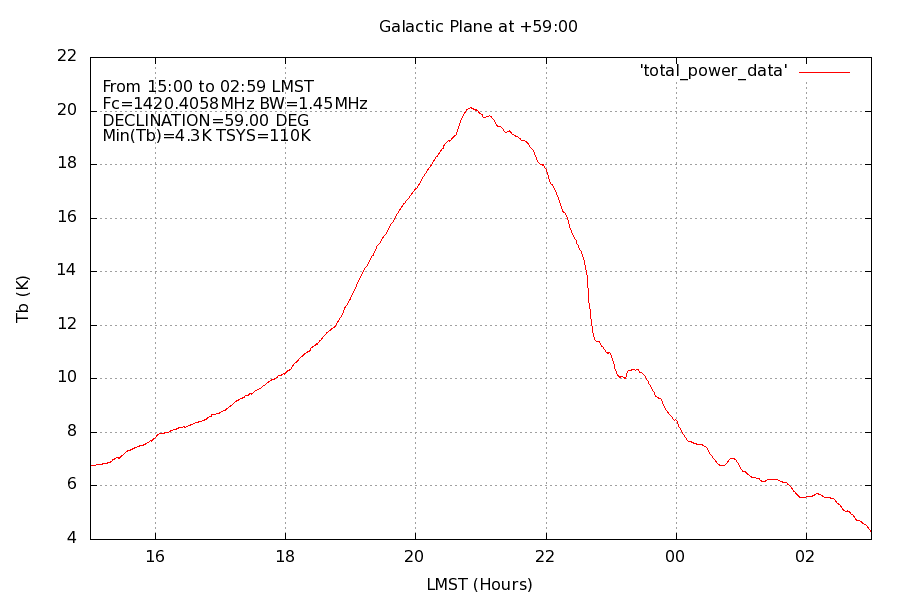
First, a little bit of sky at declination +41, with the center being in the region of Cygnus:
Then a similar bit of sky, but this one, roughly 18 degrees higher in declination. Again, the center is roughly in the region of Cassiopeia:
Another example power curve.
Both of those plots show so-called “total power” or “continuum” plots as seen by the radio telescope.
In some sense, a radio telescope is like a single-pixel light-meter, showing you the sky brightness as parts of the sky move through the beam. Both of these “continuum” plots are showing the effective sky brightness of the Galactic Plane as it moves through the beam of the instrument. Both of the above plots were produced with the “process_simple_tpat” tool that comes with simple_ra.
The processing tools have the ability to automatically overlay multiple-days data, aligned on LMST, to produce composite sky plots. This allows the ability to produce, over time, high-SNR sky maps.
Since the instrument we describe here is a Software Defined Radio, it is able to do other things as well, namely, produce spectral data at the same time as it collects continuum data.
Here is a spectrum of the hydrogen line, taken near the peak of the transit of the galactic plane near Cygnus.
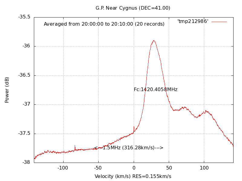
Hydrogen line spectrum indicating radial velocities.
Note how the plot is calibrated in velocity, rather than, for example MHz. The script that produces these plots, process_simple_specdat can automatically calculate the doppler shift from the data, since the data are internally annotated with respect to center frequency of the observation.
In the plot above, we can clearly see a “triple humped” spectral structure, indicating that at the time of the observation, there were three distinct hydrogen clouds within the field-of-view of the radio telescope.
Here’s a plot of a bit of hydrogen towards Auriga:
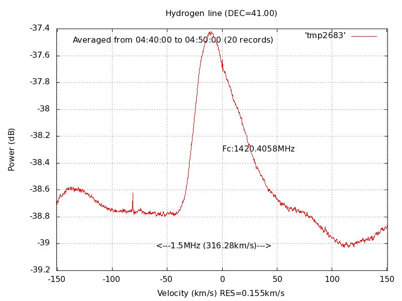
Note the excellent SNR of these plots—the simple_ra receiver application performs a fair amount of integration on the individual specta, to improve the SNR, and the process_simple_specdat script further improves the SNR by averaging all the log records within the given time window, with simple_ra normally logging high-resolution (155 meters/sec in the above plot) spectral estimates every 30 seconds.
Conclusion
Advancements in technology have allowed back-yard radio astronomers to perform observation feats that in years past might have them branded as witches. In the early 1950s, when Ewen and Purcell first confirmed the existence of the hydrogen line 7 , they had a budget of $500.00, operating out of Harvard University. In today’s dollars, that’s a roughly $4500 expenditure. Still, an outstanding ROI for a scientific observation that was of such extreme importance.
Keep in mind that Ewen and Purcell weren’t able to determine the spectrum of neutral hydrogen, just confirm that it must exist along most lines of sight through the galaxy, both confirming the theory of Van De Hulst, and at the same time laying-to-waste Van De Hulst’s statement that we’d likely never be able to observe the line, due to its very-diffuse (and thus, weak) nature.
Ewen and Purcell had an instrument with an aperture of roughly 1.2m – roughly 1.6 times the collecting area of the dish described here. Yet with an investment of less than $200.00 of today’s dollars (roughly $25.00 in 1951!), an amateur can vastly exceed the kinds of observational quality that Ewen and Purcell were able to make from the roof of a building at Harvard, back in 1951.
A project of this type is a worthwhile enterprise both for the individual, and schools both at the secondary, and post-secondary levels.
1. See, for example: http://www.gb.nrao.edu/epo/ibt.shtmlReceiver Hardware: RTLSDR
2. See: http://www.nooelec.com/store/software-defined-radio/tv28tv2.html
3.See: http://sdr.osmocom.org/trac/wiki/rtl-sdr
4. See: https://www.ettus.com/product/details/USRP%20Instant%20SDR%20B100%20Bundle%20-%20B100%20+%20WBX%20Bundle%20%2850-2200MHz%29%20+%20LiveUSB
5. See: http://www.sadoun.com/Sat/Order/Dishes/Free-to-air-satellite-dish.htm
6. See: http://angelelectronics.ca/shop/satellite/dishes/fortecstar-fc06
7. See: http://www.nrao.edu/whatisra/hist_ewenpurcell.shtml