
Memo 0001: Hydrogen line spectrometer description
Canadian Centre for Experimental Radio Astronomy http://www.ccera.ca
Memo: 0001 Hydrogen line spectrometer description
To: Interested parties
Cc: Open Source Radio Telescopes
From: Marcus Leech, mleech@ripnet.com
Date: Oct 17, 2017
Subject: A description of the dual-channel hydrogen-line spectrometer
This memorandum, the first in a series, describes the currently-deployed architecture of the dual-channel 21cm hydrogen-line spectrometer. This spectrometer is used to provide real-time spectral estimates for undergraduate lab courses in astrophysics.
The facility
The dual-channel spectrometer is situated on a rural campus near Smiths Falls, Ontario, Canada. The campus was once used to house a government institutional care program for disabled adults. The provincial government moved out of the campus in 2009, and it was subsequently acquired by a private corporation. The site occupies roughly 141 hectare (348 acres) located a few km from the downtown core of Smiths Falls. The site includes over 800,000 square feet of various types of institutional buildings, all connected together though ground-floor and basement hallways.
The Canadian Centre for Experimental Radio Astronomy arranged to rent office/lab space and copious roof space in the fall of 2016. The CCERA grew out of the notional “remains” of the Shirley’s Bay Radio Astronomy Consortium, which ceased operations in 2013 due to a loss of access to the main asset, an 18m satellite earth-station.
The location is quiet, both in terms of human activity and relevant RFI. The CCERA operates a 611Mhz interferometer at the site, in addition to the 21cm spectrometer. Neither instrument is unduly affect by RFI most of the time. The interferometer will be described in a future memo.
The early 21cm instrument
The first instrument that CCERA made operational at the site was a simple, fixed-pointing, 21cm spectrum monitor, intended purely for quick demonstration purposes. This instrument was operational within a few weeks of CCERA moving on-site, and consisted of a 0.85m dish, circular wave-guide feed, and a low-noise amplifier and filter chain feeding a AirSpy Mini SDR receiver. The instrument performed flawlessly and was only shut-own so that parts from it could be scavenged for the dual-channel instrument described below.
The dual-channel 21cm spectrometer
The CCERA had acquired a pair of 1.2m offset dishes in 2015, and the plan was to eventually use them in a 4.2GHz interferometer. But in summer 2016 a requirement emerged to support a burgeoning undergraduate astrophysics program at a local university, Carleton University. It became obvious rather-quickly that a student lab program that involved the analysis of 21cm spectral data to support calculation of the galactic rotation curve would have immediate benefit to Carleton’s astrophysics undergraduate stream. Since we had two 1.2m dishes, it seemed a simple project to operate two spectrometer instruments, with offset-pointing to allow a more rapid coverage of the sky, given our transit-type mechanical setup.
The two dishes were re-positioned on the roof to be close to one another, shown here in a recent photo.
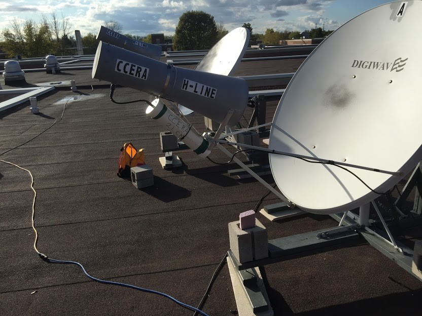
Binocular spectrometer dishes
The dishes are mounted using the manufacturer-supplied mount, with additional reinforcement. The mount is then attached to a “footing” consisting of crossed 2 x 6” lumber, with concrete half-blocks to provide adequate hold-down mass.
Elevation control is via a 14” linear actuator that is driven with a simple 18V power-supply and PWM controller. Elevation position feedback is currently via a human operator equipped with a mechanical inclinometer and a calculator. These particular dishes have a 24.6 degree offset angle, so one must factor in both local latitude and the offset angle of the dish to derive the appropriate elevation angle for a given astronomical declination during meridian transit.
The feed horns are ordinary 15cm (0.76 λ) 24ga black stove-pipe with conical extensions custom-manufactured for CCERA at a local HVAC sheet-metal shop. Show here prior to painting.
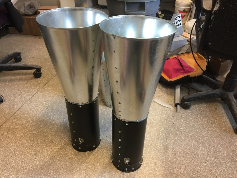
Feed horns, prior to painting
The low-noise amplifier chain for each channel consists of a TQP3M9037 evaluation PCB, followed by a 1420Mhz tubular filter, followed by an SPF-5189Z module, commonly available on eBay. The tubular filters were custom manufactured for the Algonquin Radio Observatory some time in the 1980s, and now find a home at CCERA.
The filters are attached to a piece of aluminum strip to provide connection rigidity, and the entire assembly is fitted inside standard 3” DWV PVC pipe, with end-caps and vent-holes drilled in the “downstream” direction to preclude the inevitable cryo-pumping of moisture into the enclosure.
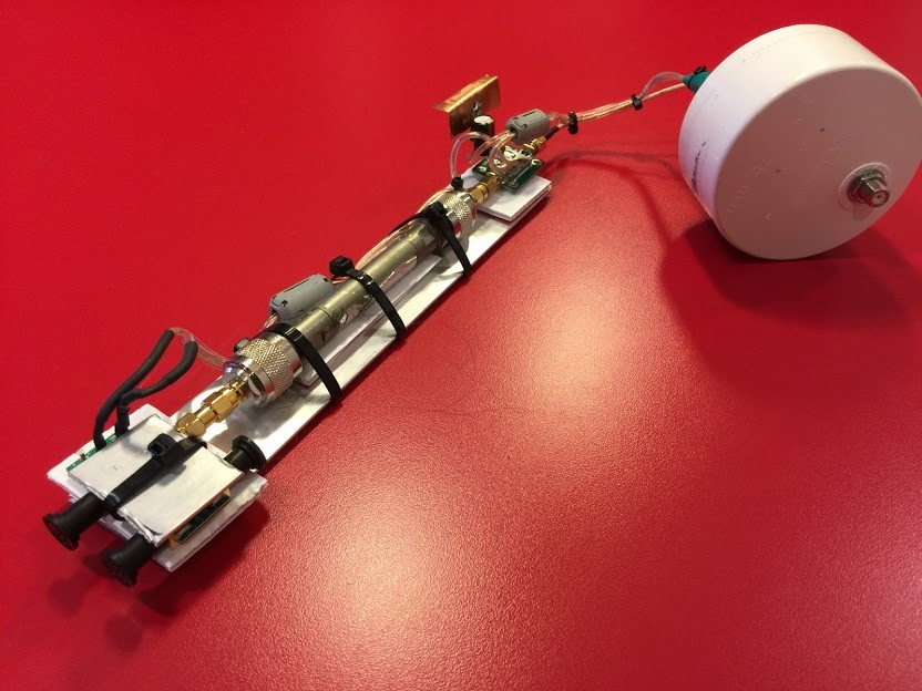
Bias-power-supply
The bias voltage for the amplifiers is provided by the use of a CATV-type bias-Tee, but used in the notional “reverse direction” from ordinary use. This directs the DC voltage into an LM705 voltage-regulator circuit, shown in the picture above with a small ad hoc copper heat-sink. DC lines are provided with ferrite clamp-on chokes to reduce common-mode noise coupling into the amplifiers.
The back-end receiver is perhaps the most complicated piece of machinery in the instrument chain, and will be described only briefly here. A more complete description will appear in a future memo in this series.
The back-end receiver is based on Software Defined Radio with tuning, sampling, and forming of a USB-2.0 digital IF signal provided by a pair of AirSpy R2 receivers, which were very graciously donated by ITEAD Studio and Youssef Touil. The receivers are connected to dedicated Odroid XU4Q single-board computers, which run Gnu Radio flow-graphs to acquire spectra with 2.5MHz of bandwidth. The AirSpy receivers use an external 10MHz reference that is provided by selecting between an “in skin” 10MHz Ovenized Crystal Oscillator or an external GPS derived 10MHz clock. The GPS source provides accuracy and stability in the order of 5PPB, while the OCXO provides accuracy and stability of approximately 30PPB. In the future, a Rubidium Lamp 10MHz reference will be used, which will provide accuracy and stability of approximately 0.1PPB. A photo showing the internal layout, including the Odroid XU4Q computers and AirSpy R2 receivers is shown below.
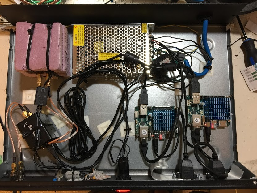
Back-end chain
A more detailed description of the signal-processing chain will appear in a future memo in this series, however, shown below is a “real time” post-processed capture of the spectrum seen by the two receiver channels.
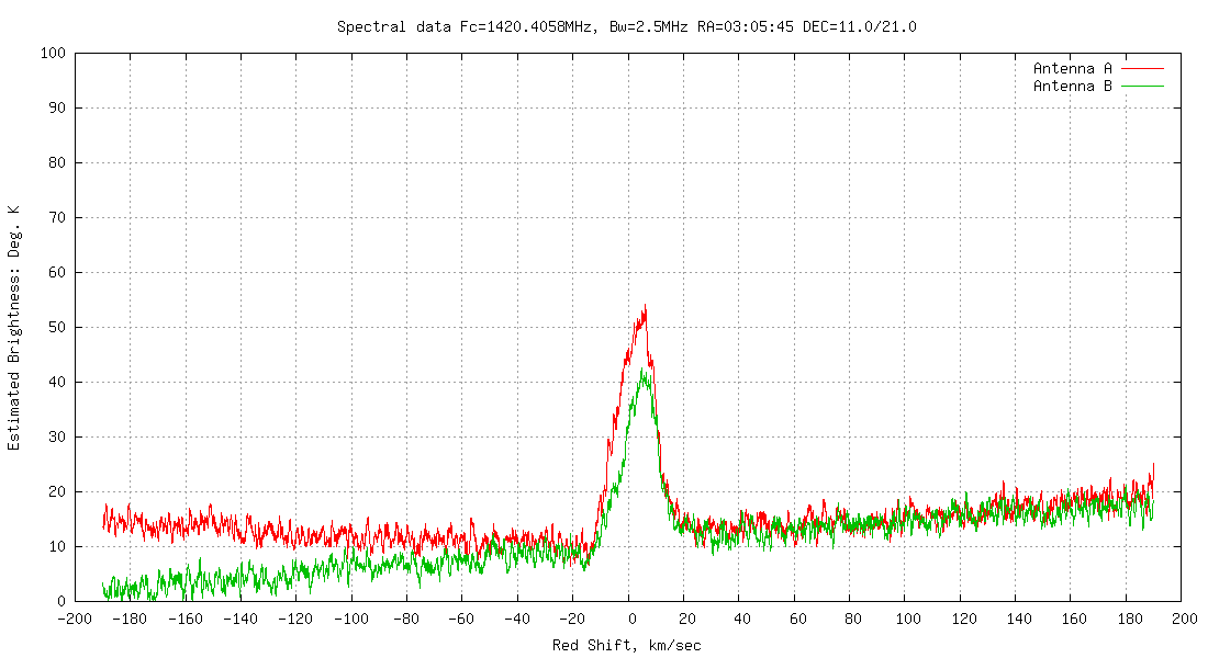
“Real-time” post-processed spectrum.
Conclusion
A viable dual-channel 21cm spectrometer instrument is briefly described along with “quick look” results.