
Memo 0009: The IDEA experiment: Amateurs looking for D1
Canadian Centre for Experimental Radio Astronomy http://www.ccera.ca
Memo: 0009 The IDEA experiment: Amateurs looking for D1
To: Interested parties
Cc: Open Source Radio Telescopes
From: Marcus Leech, mleech@ripnet.com
Date: Jun 1, 2018
Subject: Amateur attempts to observe the Deuterium line
This memorandum describes a distributed experimental approach for a group of amateur observers to loosely collaborate to observe the Deuterium line, at 327.384352 MHz.
Interstellar Deuterium
Deuterium, the isotope of Hydrogen, is estimated by Big-Bang cosmology to have a residual density with respect to plain Hydrogen of roughly 1.0e-5. That is, roughly 1 in 1.0e5 neutral hydrogen atoms in the ISM are likely to be Deuterium. We refer to this as D1, like the neutral ISM hydrogen atom is referred to as H1.
It is the case that in many parts of the sky, H1 can be detected with quite-modest equipment with impressive fidelity. For example, on a 1.2m dish antenna, with a not-horrible LNA and SDR based spectrometer, H1 will show up in the spectra after only a few 10s of seconds of integration time.
It makes sense, then, that under similar observing conditions (equivalent effective antenna area, amplifier noise temperature and RFI conditions), that an attempt to detect D1 should “merely” require an integration time that is 1.0e5 times longer.
This translates into an integration time of approximately two years, compared to a putative 30 seconds or so required for a good H1 signal.
Previous Success
Past experiments by Rogers, et al,1 near the MIT Haystack Observatory, were successful in observing D1 near the galactic anti-center.
The approach used was conceptually quite simple. A number (24) of 5×5 dipole-array “modules” acted as independent spectrometers, with digital beam-steering to track the target sky region. The modules were NOT mutually coherent, but simply improved sensitivity by sqrt(N), N being 24 in the case of the Haystack experiment.
A proposed amateur-scale attempt
We propose a conceptually-similar attempt, based on loosely-coordinated, independent, inexpensive spectrometer stations, using the North Celestial Pole as a target region.
The NCP is not known for having a large abundance of H1, but it does have enough that detection of it with modest instruments is quite easy and routine.
The NCP itself, when in the center of a telescope FOV appears to be stationary, which makes long term observing of the region a simple process, not requiring active tracking.
An instrument with a somewhat “sloppy” Field of View (FOV) is easy to construct, and when pointed at the NCP region, will have a significant area with the field, including areas with nontrivial amounts of H1. We estimate that an antenna with a 10-20° field would be ideal. This is not much larger than the single-module FOV used by the Haystack instrument.
The proposal, then, would be for a number of distributed stations to establish antennae of suitable parameters pointed at the NCP, and attach these antennae to a suitable spectrometer system and gather spectral data over an extended time period, largely uninterrupted.
We have elected to call this distributed experiment IDEA. The International Deuterium Experiment for Amateurs.
Antenna Considerations
According to an interesting treatise on antenna theory2 the maximum gain of ANY antenna that can fit inside a given sphere describing its maximum dimension is strictly limited.
This means that one can analyze possible designs in terms of the “largest tolerable sphere size”. It is tempting to consider “the usual suspecs” for antennae, including Yagi-Uda antennae and parabolic dish antennae, as well as large broad-side arrays.
In the end, the individual experimenter will have to make up their mind for themselves, but the requirement is for roughly 15-18dBi gain, giving a suitable field-of-view size for the antenna.
One of the surprises in this search is the 3d-corner reflector antenna. Normally considered for microwave work, but also entirely practical for low-UHF experiments like the one at hand. The advantage of a 3d corner reflector design is that it is very easy to build and get working. A disadvantage is that the gain increases non-linearly towards a limit proportional to lambda. It turns out that a 3d corner reflector that is 2.8 lambda is nearly indistinguishable from one that is 3.2 lambda or 4.2 lamba, etc. The “sweet spot” for construction at our design frequency (92cm), is approximately 2 lambda, or 1.8m, or 6ft.
Construction of side and bottom panels from lumber and chicken-wire would be straightforward and inexpensive. The launch angle of such an antenna is at 45 degrees from each surface. This, purely coincidentally, would mean that such an antenna placed pointing northwards, with the base flat on the ground, would naturally point at the NCP, due to the happenstance of our local latitude (44.9° north).
The illuminating monopole for such an antenna is placed roughly 0.6 lambda from the vertex of the side panels, attached to the bottom panel, with the monopole being approximately 0.75 lambda long.
More design information on the so-called truncated form of this antenna can be seen in an article published in QSL magazine, by Dragoslav Dobričić, YU1AW3
A rough sketch is shown below.
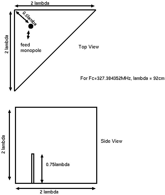
3D Corner Reflector
Other antennae with roughly-similar gain properties will, of course, work admirably. Anyone with a 3m-12m dish that is otherwise-idle could press that dish into service readily, using perhaps a loop feed or even a simple dipole with a backing groundplane.
Low Noise Amplifiers
The primary concern with the required low-noise amplifier is dynamic range, since the low-end of UHF even in “quiet” locations can still be pretty “full”.
Fortunately, the commercial world has the same problems with linearity, and modern, inexpensive, MMIC amplifiers, such as the SPF-5189Z are readily available. Pre-packaged units with connectors on a PCB are readily available from eBay and Amazon.
A two-stage approach, with a filter in between the two stages should be more than adequate to drive fairly-long coaxial cables at this frequency.
Filters
Filters for this frequency are somewhat rare, but not entirely non-existent. There have in the past been radio-based systems that use 327.5MHz and 327.8MHz, so there are SAW filters whose bandwidth covers the desired frequency range “around”.
The SAW filters in this case would be used between LNA stages to try to eliminate any tendency for the ultimate back-end receiver system to produce intermodulation products.
It is also quite likely that some type of low-loss, but broader-band, filter will be required between the antenna and LNA in many locations. Good-quality cavity filters with custom tunings are available from various Chinese suppliers (through Alibaba) for roughly US$60.00 each.
Another approach is to use a series of quarter-wave stubs in front of the LNA. Perhaps one stub providing a bandpass at the notional Fc, and a pair of other stubs providing notch responses either side. Such filter architectures aren’t difficult to produce, and are low-loss. But the work on something like that may exceed the cost of simply having a few cavity filters made in China.
This author has previously used the Made-in-China approach for 611MHz filters used in front of our LNAs in the CCERA 611MHz interferometer with excellent results.
Receiver systems
The required bandwidth for a receiving system for the D1 line is quite modest. For galactic hydrogen a total Doppler frequency range of roughly 2MHz is usually assumed, and for D1, that range would be roughly 4.3 times smaller, or 460kHz. We know, however, that the range of Doppler velocities in the NCP area are modest—on the order of 5 to 10km/sec. This means that the Doppler shift of the “line” would be on the order of 10kHz.
We propose that the ultimate FFT bandwidth would be about 10 times this, or 100kHz. Existing cheap, SDR-based, receivers can easily meet these requirements. In particular the RTLSDR type devices are ubiquitous, cheap, and easy to interface to software systems like Gnu Radio4.
The RTL-SDR type devices have relatively-poor oscillator precision, at approximately 100ppm. This precision (and related stability) is entirely adequate for this type of rough qualitative observation, but the keen can easily modify the devices to use a shared 28.8MHz reference clock of substantially-higher quality. Such oscillators are routinely available on eBay for roughly $10.00 each, and one can connect a number of RTL-SDR devices to a single clock.
Computational requirements
The computational requirements for computing spectra over a bandwidth of 100kHz are very modest indeed.
We created a simple proof of concept signal flow in Gnu Radio which brings signals in from 3 RTL-SDR radios at 1Msps each. It then shifts the signal slightly away from the inevitable DCoffset artifact, and filters-and-decimates down to 100ksps. It then computes the 2048-bin FFTs at “real-time” rates, and dumps the data into a NULL SINK for test purposes. The result consumed roughly 30% of the available CPU on an Odroid C1 single-board computer, along with consuming perhaps 15% of the available memory. This means that a keen observer could use this configuration to process spectra from three, or perhaps four antennae simultaneously, with a computer that costs US$49.95 in single-unit quantities, with receivers that are available on outlets like eBay for U$10.00 each.
Data requirements
The data requirements are quite modest. Since the integration times are very long, each instrument need only provide an integrated spectrum every few minutes at the very most.
Each spectral “record” if rendered into a text-based format like .csv would be approximately 20-30k bytes, depending on numerical formats, etc.
If we assume one of these records every 5 minutes, that’s 8Mbyte/day/station, or 3.2Gbyte/year/station. A station with multiple antennae may choose to average their antennae data together prior to logging.
If we assume a participation level of 100 stations, that is only 320Gbyte/year for the entire “system”. It may be the case that some type of “cloud” storage solution would be ideal for coordinating data storage, and if so, it would still be fairly cheap (perhaps $10.00/month for storage of data across the entire system).
Data analysis
At some point in time, a grand coordination of data sets will be required, and that will require developing algorithms for RFI excision, baseline subtraction, etc.
But that event would occur at the earliest perhaps a year after the start of the project. Specific strategies can be developed as data arrives from stations, to identify non-ideal data and excise it and process it appropriately. But the main thing, up front, is to acquire the data with as much quality as can be achieved with a project that is:
- Low budget
- Highly distributed
- Uncertain outcome
Ideal station characteristics
An ideal station is situated in an area of lower population, far away from large urban centers and sources of RFI. Such a station would need access to the Internet, but not at blindingly high speeds.
Indeed, one could imagine a “remote” station where data are accumulated for weeks at a time, with manual shuffles of physical media and a data upload performed close to “civilization”.
Stations will require adequate time-keeping, but not at scales one would have to consider for VLBI. Records would be tagged with LMST so that they can be coordinated post facto. If the station is able to maintain time to within a few seconds of UTC, that should be adequate. If a station has a reliable internet connection, then the use of NTP would be strongly encouraged.
Access to the NCP becomes more awkward as one moves further south in latitude. Any station in the band from 20N to perhaps 60N latitude would be a good candidate.
Conclusion
We propose a large-scale, low-budget, loosely-collaborative project to detect the D1 line in the region of the North Celestial Pole.
Rough analysis suggests that the project has a modest probability of success, with individual investments being quite low.
Comments and suggestions are enthusiastically encouraged.
1 See: https://www.haystack.mit.edu/ast/arrays/deut/deut_memos/memoindex.html
2 L. J. Chu. Physical limitations of omni-directional antennas. Journal of Applied Physics, vol. 19, December 1948. Pages 1163-1175.
3 www.qsl.net/yu1aw/ANT_VHF/shorten3dcra.pdf
4 See: http://www.gnuradio.org