
Memo 0002: Observations on ad-hoc circular waveguide for 21cm measurements.
Canadian Centre for Experimental Radio Astronomy http://www.ccera.ca
Memo: 0002 Observations on ad-hoc circular waveguide for 21cm measurements.
To: Interested parties
Cc: Open Source Radio Telescopes
From: Marcus Leech, mleech@ripnet.com
Date: Oct 20, 2017
Subject: Some quick observations of the properties of ad-hoc waveguides made from common HVAC duct.
This memorandum describes some quick laboratory measurements of two different sizes of HVAC duct for use as 21cm circular waveguides.
Cheap circular wave-guides
Short sections of circular wave-guide are a popular choice among amateur observers for use as feed antennae for parabolic dishes.
It is often the case that the amateur observer will choose inexpensive materials, like galvanized circular duct-work as a circular waveguide—certainly not as efficient as a similar piece of silver-plated aluminum or copper, but light-weight, easy to work with, and quite inexpensive.
For the observer operating at 21cm, it has become near-gospel to use a guide with a diameter very close to 15cm (6”). This gives an aperture near 0.75 lambda at 21cm, which provides good illumination properties for dishes with F/D in the range 0.3 to 0.4.
A wave-guide with a diameter of 15cm also affords a guide-cutoff frequency near 1100MHz, which reduces or eliminates potential RFI from various sources below that frequency.
Theory tells us that as the guide diameter decreases, the guide-cutoff frequency increases. Eventually as you make the guide smaller the cut-off frequency is above your operating frequency, making propagation impossible.
The following VSWR plot shows this quite well for a 15cm (6”) diameter HVAC-duct circular feed that was 30cm long, with an HVAC end-cap on one end, a 58mm-long, 7mm diameter probe located 54mm from the back-plate.
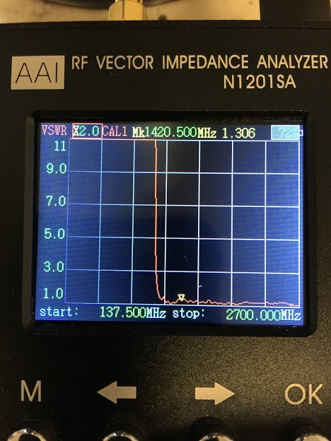
One can easily see that the inflection point in SWR is nearly 400Mhz below our marker frequency at 1420.500MHz.
Next, we measured the VSWR under identical conditions of probe-placement, length, and thickness, but with a 5” HVAC duct as our waveguide. The results are shown below.
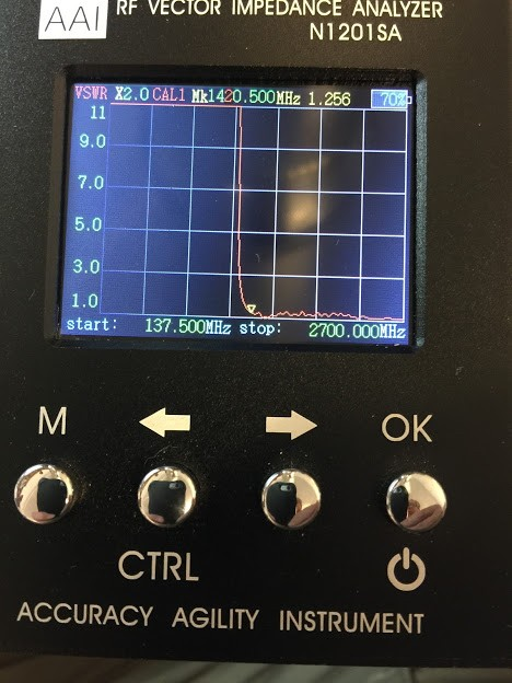
You can see that the inflection-point in VSWR is roughly 200MHz higher in the above image.
Clearly, there is some filtering advantage to using a slightly-smaller waveguide.
A potential disadvantage is that the illumination angle of a 5” guide is slightly larger than a 6” guide, but one can adjust the illumination angle with a simple HVAC tapered reducer fitting, to bring the effective aperture outwards a bit.
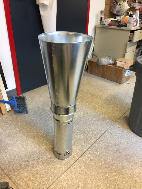
We experimentally fitted up a full feed for our 1.2m offset-fed dishes, using an expander cone, and the 5” circular HVAC waveguide:
The top cone was custom-made by a local HVAC shop, and you can see the interstitial 5” to 6” tapered adapter — a standard commercial item.
Rough Conclusions
Using 5” HVAC ducting as a “critically matched” wave-guide for 21cm appears to be viable. Some mechanism to effect a useful low-pass response in front of the first LNA, with very low loss, would still be desirable.